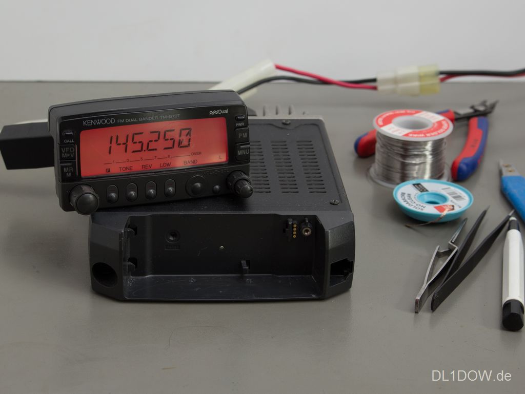
Kenwood TM-G707E with red background lighting and self-made separation cable
(click to enlarge)
The Kenwood TM-G707 is a dual band transceiver for 2 m and 70 cm band. Its main advantage is its magnificent handling.
Some transceivers are well-known for their high-performance receiver capabilities. Some rigs are bought because of their overwhelming number of features or because of high transmitting power in all bands. And there are some rigs, which have none of this — they just offer perfect handling.
The Kenwood TM-G707E is the second ham radio transceiver I ever bought. Its usability makes it the exact opposite of my first transceiver, a Sommerkamp TS-220 DX and the ICOM IC706mkIIG which came after it. One gets used to it the very first seconds after not having used if for years. All control elements are large enough to be used with gloves, and it's no problem to operate this rig blindly. This makes this rig the perfect mobile transceiver despite its other flaws.
The Kenwood TM-G707E was shipped with a bright amber coloured background lighting. Back in these days, LEDs in this colour provided the brightest visual impression for a given energy consumption. When a transceiver is mounted into a car, maximum brightness is not always considered of major importance. Sometimes, it's preferred more that the colour matches the dashboard lighting.
To match the dashboard lighting, I used my phone's screen and a website[1], which demonstrates the colour of different light wavelengths. A LCD screen is not perfect to visualize the visible light spectrum, especially in the domain of red colour, but for my application, this has been sufficient, so I purchased red LEDs with a wavelength of 635nm and 28 mcd in 2012 (metric) or 0805 (imperial) SMT package.
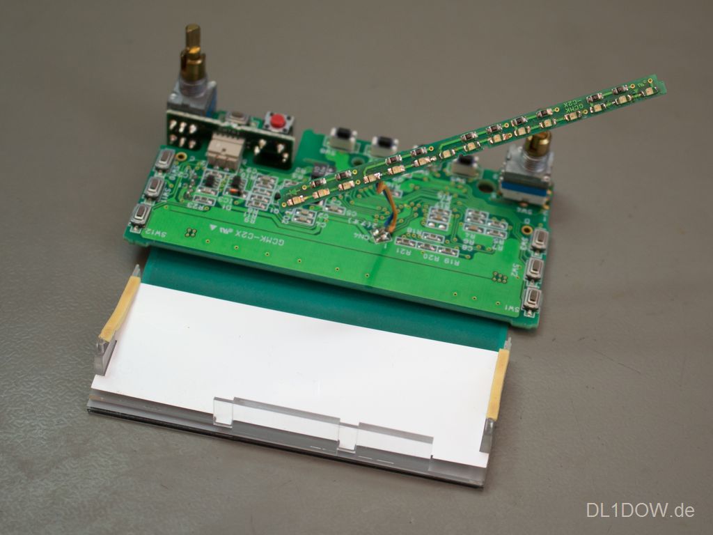
The background lighting of the TM-G707E consists of 15 LEDs on a separate PCBs below a semi-transparent light diffusor. They are connected in groups of three with two series resistors. All LEDs have the same aligned polarity. All in all, it's not that big deal to change them.
The control panel of the Kenwood TM-G707E is detachable by design. However, the separation kit, which was sold under the label “DFK-3C”, “DFK-4C” or “DFK-4C” was sold unreasonable expensive, so it's hard to get one of those nowadays. In the age of 3D-printers, it shouldn't be a problem to design such a connector with some patience and pogo pins. But since I do not own such a device and do not have any ambitions to keep my rig in mint condition, I chose another way.
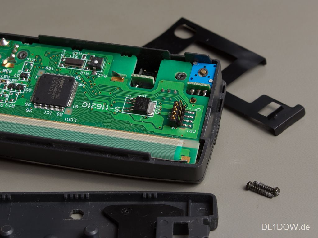
Originally, the control panel is connected to the transceiver by spring-loaded connectors. Having a look at the PCBs, there are 4 lines in next to them. Adding a 2.0 mm pitch SMT pin header is possible after removing the solder resist with a glass fibre pencil. Since these wide line are close to drilled solder pads, there is little risk that the new connector will overstress the circuit lines on the PCB.
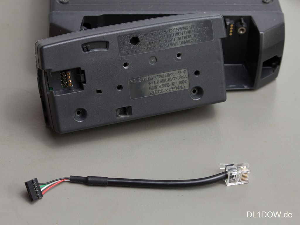
The cut-out in the housing has been widened for the additional connector using a jigsaw. Even with the pins of second connector being longer than the original ones, it's still possible to mount the front panel in its original place.
Inside the transceiver, it's easy to identify the appropriate four lines to attach another pigtail.